To power the successors of Espgaluda, CAVE designed a new hardware platform based on the powerful Hitachi SH-3 processor. The graphics are handled by a dedicated FPGA and the protection resides in a CPLD. There are no more EPROM DIL sockets, instead all of the software is stored in FLASH. The PCB is equipped with an EEPROM which saves your high scores. This is a generic platform which can be reprogrammed by CAVE using JTAG technology. I.e. an Ibara may be converted to a Mushihimesama if desired
However it looks as if U23 & U24 (Sound Data) are not a part of the JTAG chain and are most likely preprogrammed before mounting. |
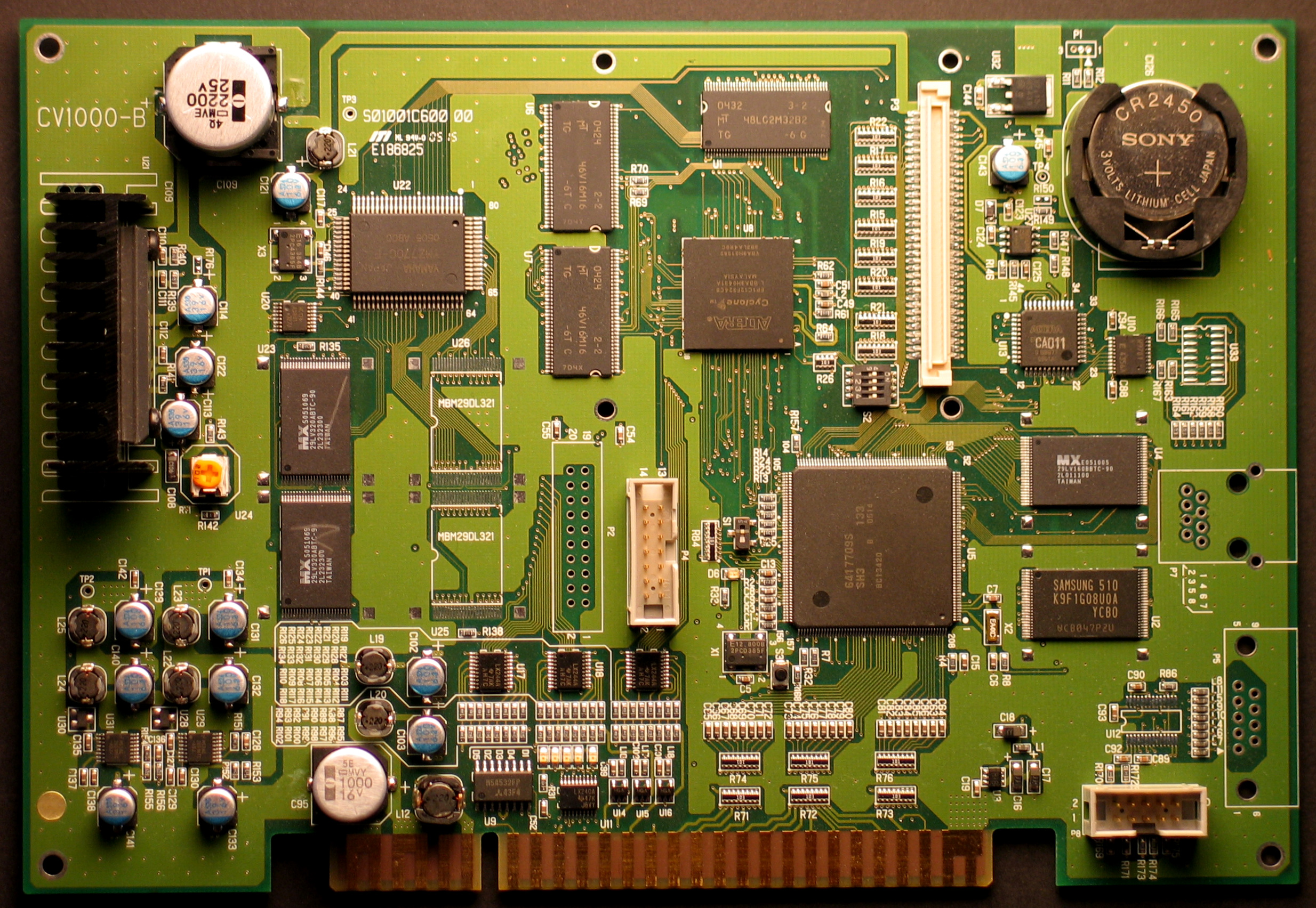
| PCB |
CV1000-B |
| C126 (BATTERY) |
CR 2450, Powers the RTC (Real Time Clock) U10. Look at the garden clock in Ibara. |
| U21 (AMPLIFIER) |
LA 4708 |
U5 (CPU) |
Hitachi SH-3 @ 133 MHz (7709S) |
| U22 (SOUND CHIP) |
Yamaha YMZ770C-F
|
| U23-U24 (FLASH) |
MBM 29DL321, 32 MBit CMOS 3.0V, Sound data. |
| U6 (SDRAM) |
MT46V16M16 – 4 MBit x 16 x 4 banks,
RAM (256 MBit) |
| U7 (SDRAM) |
MT46V16M16 – 4 MBit x 16 x 4 banks,
RAM (256 MBit) |
U1 (SDRAM)
|
MT48LC2M32 – 512K x 32 x 4 banks, (64 MBit) |
U8 (FPGA)
|
Altera Cyclone EP1C12 FPGA |
| U13 (CPLD) |
Altera EPM7032 (MAX 7000 Series), Most likely the protection chip. |
| U4 (FLASH) |
29LV160BB 16M-BIT CMOS
3.0, Boot device, FPGA bit file, main program code |
| U2 (FLASH) |
K9F1G08U0M 128M x 8 Bit / 64M x 16 Bit NAND. Graphics
data. |
| U27 (SUPERVISOR) |
MAX 690S 3.0V Microprocessor Supervisory Circuit |
| U10 (RTC & EEPROM) |
RTC 9701, Serial RTC Module with EEPROM 4 kbit (256x16 bit), controlled by U13 |
| U12 (RS-232 TRANCEIVER) |
MAX 3244E RS-232 Tranceiver, only mounted when P5 is mounted |
| S3 (MICRO PUSH BUTTON) |
Test switch, same as on the JAMMA connector |
| S1 (DIL SWITCH) |
Half Pitch DIL Switch x 1, function unknown |
| S2 (DIL SWITCH) |
Half Pitch DIL Switch x 4, SW1=Setup, other switches unknown |
| P2 (IDC CONNECTOR 20 PIN) |
function unknown, P2 is not always mounted |
| P4 (IDC CONNECTOR 14 PIN) |
JTAG connector |
| P8 (IDC CONNECTOR 10 PIN) |
Advanced User Debugger |
| P3 (CONNECTOR) |
Most likely an expansion port, P3 is not always mounted |
| P5 (CONNECTOR) |
Most likely a serial connector. Only mounted on early Mushihimesama PCB's |
| P7 (CONNECTOR) |
Network port pinout. Never seen mounted on any PCB. |
| D1-D6 (LED) |
Status LED's. D6 lights up at power on then shuts off, D2 indicates coinage. |
